 SPIM can read and immediately execute files containing
assembly language or MIPS executable files. SPIM is a self-contained
system for running these programs and contains a debugger and
interface to a few operating system services.
`` the performance at none of the cost''
James R. Larus
larus@cs.wisc.edu
Computer Sciences Department
University of Wisconsin--Madison
1210 West Dayton Street
Madison, WI 53706, USA
608-262-9519
Copyright © 1990--1993 by James R. Larus
(This document may be copied without royalties,
so long as this copyright notice remains on it.)
April. 12, 1993
(Revision 11 corresponding to SPIM Version 5.1)
SPIM S20 is a simulator that runs programs for the MIPS R2000/R3000
RISC computers. SPIM can read and immediately execute files containing
assembly language or MIPS executable files. SPIM is a self-contained
system for running these programs and contains a debugger and
interface to a few operating system services.
The architecture of the MIPS computers is simple and regular, which makes it easy to learn and understand. The processor contains 32 general-purpose registers and a well-designed instruction set that make it a propitious target for generating code in a compiler.
However, the obvious question is: why use a simulator when many people have workstations that contain a hardware, and hence significantly faster, implementation of this computer? One reason is that these workstations are not generally available. Another reason is that these machine will not persist for many years because of the rapid progress leading to new and faster computers. Unfortunately, the trend is to make computers faster by executing several instructions concurrently, which makes their architecture more difficult to understand and program. The MIPS architecture may be the epitome of a simple, clean RISC machine.
In addition, simulators can provide a better environment for low-level programming than an actual machine because they can detect more errors and provide more features than an actual computer. For example, SPIM has a X-window interface that is better than most debuggers for the actual machines.
Finally, simulators are an useful tool for studying computers and the programs that run on them. Because they are implemented in software, not silicon, they can be easily modified to add new instructions, build new systems such as multiprocessors, or simply to collect data.
The MIPS architecture, like that of most RISC computers, is difficult to program directly because of its delayed branches, delayed loads, and restricted address modes. This difficulty is tolerable since these computers were designed to be programmed in high-level languages and so present an interface designed for compilers, not programmers. A good part of the complexity results from delayed instructions. A delayed branch takes two cycles to execute. In the second cycle, the instruction immediately following the branch executes. This instruction can perform useful work that normally would have been done before the branch or it can be a nop (no operation). Similarly, delayed loads take two cycles so the instruction immediately following a load cannot use the value loaded from memory.
MIPS wisely choose to hide this complexity by implementing a virtual machine with their assembler. This virtual computer appears to have non-delayed branches and loads and a richer instruction set than the actual hardware. The assembler reorganizes (rearranges) instructions to fill the delay slots. It also simulates the additional, pseudoinstructions by generating short sequences of actual instructions.
By default, SPIM simulates the richer, virtual machine. It can also
simulate the actual hardware. We will describe the virtual machine
and only mention in passing features that do not belong to the actual
hardware. In doing so, we are following the convention of MIPS
assembly language programmers (and compilers), who routinely take
advantage of the extended machine. Instructions marked with a dagger
( ) are pseudoinstructions.
SPIM provides a simple terminal and a X-window interface. Both provide equivalent functionality, but the X interface is generally easier to use and more informative.
spim, the terminal version, and xspim, the X version, have the following command-line options:
The terminal interface ( spim) provides the following commands:
Most commands can be abbreviated to their unique prefix e.g., ex, re, l, ru, s, p. More dangerous commands, such as reinitialize, require a longer prefix.

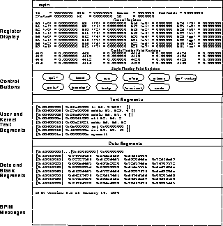
Figure 1: X-window interface to SPIM.
The X version of SPIM, xspim, looks different, but should operate in the same manner as spim. The X window has five panes (see Figure 1). The top pane displays the contents of the registers. It is continually updated, except while a program is running.
The next pane contains the buttons that control the simulator:
The next two panes display the memory contents. The top one shows
instructions from the user and kernel text segments. The
first few instructions in the text segment are startup code (
__start) that loads argc and argv into registers and
invokes the main routine.
The lower of these two panes displays the data and stack segments. Both panes are updated as a program executes.
The bottom pane is used to display messages from the simulator. It does not display output from an executing program. When a program reads or writes, its IO appears in a separate window, called the Console, which pops up when needed.
Although SPIM faithfully simulates the MIPS computer, it is a simulator and certain things are not identical to the actual computer. The most obvious differences are that instruction timing and the memory systems are not identical. SPIM does not simulate caches or memory latency, nor does it accurate reflect the delays for floating point operations or multiplies and divides.
Another surprise (which occurs on the real machine as well) is that a pseudoinstruction expands into several machine instructions. When single-stepping or examining memory, the instructions that you see are slightly different from the source program. The correspondence between the two sets of instructions is fairly simple since SPIM does not reorganize the instructions to fill delay slots.
Comments in assembler files begin with a sharp-sign ( #). Everything from the sharp-sign to the end of the line is ignored.
Identifiers are a sequence of alphanumeric characters, underbars ( _), and dots ( .) that do not begin with a number. Opcodes for instructions are reserved words that are not valid identifiers. Labels are declared by putting them at the beginning of a line followed by a colon, for example:
        .data
  item: .word 1
        .text
        .globl main             # Must be global
  main: lw $t0, item
Strings are enclosed in double-quotes ( "). Special characters in strings follow the C convention:
    newline        \n
    tab            \t
    quote          \"
SPIM supports a subset of the assembler directives provided by the MIPS assembler:
 byte
boundary. For example, .align 2 aligns the next value on a word
boundary. .align 0 turns off automatic alignment of
.half, .word, .float, and .double directives until
the next .data or .kdata directive.
SPIM provides a small set of operating-system-like services through
the system call ( syscall) instruction. To request a service, a
program loads the system call code (see Table 1) into
register $v0 and the arguments into registers
$a0 $a3 (or $f12 for floating point values).
System calls that return values put their result in register
$v0 (or $f0 for floating point results). For example, to
print `` the answer = 5'', use the commands:
        .data
  str:  .asciiz "the answer = "
        .text
        li $v0, 4        # system call code for print_str
        la $a0, str      # address of string to print
        syscall          # print the string

        li $v0, 1        # system call code for print_int
        li $a0, 5        # integer to print
        syscall          # print it
print_int is passed an integer and prints it on the console. print_float prints a single floating point number. print_double prints a double precision number. print_string is passed a pointer to a null-terminated string, which it writes to the console.
read_int, read_float, and read_double read an entire line of input up to and including the newline. Characters following the number are ignored. read_string has the same semantics as the Unix library routine fgets. It reads up to n-1 characters into a buffer and terminates the string with a null byte. If there are fewer characters on the current line, it reads through the newline and again null-terminates the string. Warning: programs that use these syscalls to read from the terminal should not use memory-mapped IO.
sbrk returns a pointer to a block of memory containing n additional bytes. exit stops a program from running.

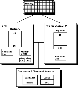
Figure 2: MIPS R2000 CPU and FPU
A MIPS processor consists of an integer processing unit (the CPU) and a collection of coprocessors that perform ancillary tasks or operate on other types of data such as floating point numbers (see Figure 2). SPIM simulates two coprocessors. Coprocessor 0 handles traps, exceptions, and the virtual memory system. SPIM simulates most of the first two and entirely omits details of the memory system. Coprocessor 1 is the floating point unit. SPIM simulates most aspects of this unit.

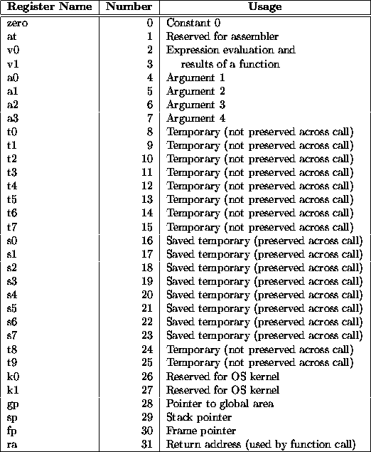
Table 2: MIPS registers and the convention governing their use.
The MIPS (and SPIM) central processing unit contains 32 general purpose registers that are numbered 0--31. Register n is designated by $n. Register $0 always contains the hardwired value 0. MIPS has established a set of conventions as to how registers should be used. These suggestions are guidelines, which are not enforced by the hardware. However a program that violates them will not work properly with other software. Table 2 lists the registers and describes their intended use.
Registers $at (1), $k0 (26), and $k1 (27) are reserved for use by the assembler and operating system.
Registers $a0-- $a3 (4--7) are used to pass the first four arguments to routines (remaining arguments are passed on the stack). Registers $v0 and $v1 (2, 3) are used to return values from functions. Registers $t0-- $t9 (8--15, 24, 25) are caller-saved registers used for temporary quantities that do not need to be preserved across calls. Registers $s0-- $s7 (16--23) are callee-saved registers that hold long-lived values that should be preserved across calls.
Register $sp (29) is the stack pointer, which points to the
first free location on the stack. Register $fp (30) is the
frame pointer. Register $ra (31) is written with the return address
for a call by the jal instruction.
Register $gp (28) is a global pointer that points into the middle of a 64K block of memory in the heap that holds constants and global variables. The objects in this heap can be quickly accessed with a single load or store instruction.
In addition, coprocessor 0 contains registers that are useful to handle exceptions. SPIM does not implement all of these registers, since they are not of much use in a simulator or are part of the memory system, which is not implemented. However, it does provide the following:

These registers are part of coprocessor 0's register set and are accessed by the lwc0, mfc0, mtc0, and swc0 instructions.

Figure 3: The Status register.
Figure 3 describes the bits in the Status register that are implemented by SPIM. The interrupt mask contains a bit for each of the five interrupt levels. If a bit is one, interrupts at that level are allowed. If the bit is zero, interrupts at that level are disabled. The low six bits of the Status register implement a three-level stack for the kernel/user and interrupt enable bits. The kernel/user bit is 0 if the program was running in the kernel when the interrupt occurred and 1 if it was in user mode. If the interrupt enable bit is 1, interrupts are allowed. If it is 0, they are disabled. At an interrupt, these six bits are shifted left by two bits, so the current bits become the previous bits and the previous bits become the old bits. The current bits are both set to 0 (i.e., kernel mode with interrupts disabled).
Figure 4 describes the bits in the Cause registers. The five pending interrupt bits correspond to the five interrupt levels. A bit becomes 1 when an interrupt at its level has occurred but has not been serviced. The exception code register contains a code from the following table describing the cause of an exception.

Processors can number the bytes within a word to make the byte with the lowest number either the leftmost or rightmost one. The convention used by a machine is its byte order. MIPS processors can operate with either big-endian byte order:

or little-endian byte order:

SPIM operates with both byte orders. SPIM's byte order is determined by the byte order of the underlying hardware running the simulator. On a DECstation 3100, SPIM is little-endian, while on a HP Bobcat, Sun 4 or PC/RT, SPIM is big-endian.
MIPS is a load/store architecture, which means that only load and store instructions access memory. Computation instructions operate only on values in registers. The bare machine provides only one memory addressing mode: c(rx), which uses the sum of the immediate (integer) c and the contents of register rx as the address. The virtual machine provides the following addressing modes for load and store instructions:

Most load and store instructions operate only on aligned data. A quantity is aligned if its memory address is a multiple of its size in bytes. Therefore, a halfword object must be stored at even addresses and a full word object must be stored at addresses that are a multiple of 4. However, MIPS provides some instructions for manipulating unaligned data.
The organization of memory in MIPS systems is conventional. A program's address space is composed of three parts (see Figure 5).
At the bottom of the user address space (0x400000) is the text segment, which holds the instructions for a program.
Above the text segment is the data segment (starting at 0x10000000), which is divided into two parts. The static data portion contains objects whose size and address are known to the compiler and linker. Immediately above these objects is dynamic data. As a program allocates space dynamically (i.e., by malloc), the sbrk system call moves the top of the data segment up.
The program stack resides at the top of the address space (0x7fffffff). It grows down, towards the data segment.
The calling convention described in this section is the one used by gcc, not the native MIPS compiler, which uses a more complex convention that is slightly faster.

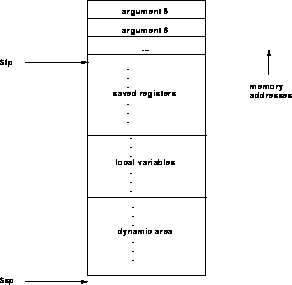
Figure 6: Layout of a stack frame. The frame pointer points just
below the last argument passed on the stack. The stack pointer points
to the first word after the frame.
Figure 6 shows a diagram of a stack frame. A frame consists of the memory between the frame pointer ( $fp), which points to the word immediately after the last argument passed on the stack, and the stack pointer ( $sp), which points to the first free word on the stack. As typical of Unix systems, the stack grows down from higher memory addresses, so the frame pointer is above stack pointer.
The following steps are necessary to effect a call:
Within the called routine, the following steps are necessary:
Finally, to return from a call, a function places the returned value into $v0 and executes the following steps: