The Link Layer

Tom Kelliher, CS 325

May 2, 2011

Administrivia

Announcements

Assignment

Read 6.1-6.3.

Projects due Wednesday at beginning of class.

Two or more review questions due Friday morning.

Assignment VII due at beginning of exam on May 12.

Senior grades.

From Last Time

Routing.

Outline

  1. Introduction.

  2. Multiple Access protocol -- CSMA/CD.

  3. Link layer addressing.

  4. Ethernet.

  5. Link layer switches.

Coming Up

Wireless networking.

Introduction

Link layer exists between hosts on either side of a single link:

\includegraphics[width=5in]{Figures/fig05_01.eps}

Unit of exchange is a packet/frame/datagram. Physical layer exchanges individual bits.

Example technologies: Ethernet, ATM, 802.11.

Error detection/correction codes appended frame:

\includegraphics[width=4in]{Figures/fig05_04.eps}

Link layer services:

  1. Framing -- encapsulation.

  2. Link access -- protocols for shared access links.

  3. Reliable delivery -- important for media with high error rates (802.11).

    Error detection/correction.

  4. Flow control.

  5. Duplex -- half or full?

Multiple Access Protocol -- CSMA/CD

How do you control transmission in a shared access medium?:

\includegraphics[width=4in]{Figures/fig05_09.eps}

A number of possible ideas:

  1. Take turns: fixed intervals, or a request protocol.

    Time division multiplexing.

  2. Partition the bandwidth.

    Frequency division multiplexing.

  3. Code division multiplexing.

  4. Random access protocols:
    1. Listen. If no stations sending, begin to send.

      If a station is sending, wait a random amount of time, then listen again.

    2. Possible for two senders to begin sending. Action upon detection of collision?

      Is it always possible to detect a sending collision?

  5. CSMA/CD -- Carrier Sense Multiple Access/Collision Detection:
    1. Sense media for idle state. If idle, begin transmitting.

      If media isn't idle, backoff for a randomly chosen unit of time.

    2. How can collisions occur?

      \includegraphics[width=4in]{Figures/fig05_14.eps}

Link Layer Addressing

  1. Each network adapter has an eight byte MAC address:
    bluebird:~/Class/Cs325/Lectures
    % ifconfig eth0
    eth0      Link encap:Ethernet  HWaddr 00:1A:A0:16:65:8B  
              inet addr:10.67.1.26  Bcast:10.67.1.255  Mask:255.255.255.0
              inet6 addr: fe80::21a:a0ff:fe16:658b/64 Scope:Link
              UP BROADCAST RUNNING MULTICAST  MTU:1500  Metric:1
              RX packets:295533 errors:0 dropped:0 overruns:0 frame:0
              TX packets:173558 errors:0 dropped:0 overruns:0 carrier:0
              collisions:0 txqueuelen:1000 
              RX bytes:139988511 (133.5 MiB)  TX bytes:31578020 (30.1 MiB)
              Interrupt:177
    
    MAC addresses are ``unique.''

  2. Each host on a network has an IP address and a MAC address:

    \includegraphics[width=5in]{Figures/fig05_17.eps}

    Why both?

    MAC addresses are not hierarchical, beyond vendor/adapter number designation.

  3. So you want to send a datagram to IP address w.x.y.z. At the link layer, you really need the MAC address. How do we get that?

    Use ARP!!

    An ARP cache:

    bluebird:~/Class/Cs325/Lectures
    % arp
    Address                  HWtype  HWaddress           Flags Mask  Iface
    10.67.1.1                ether   00:13:5F:C4:B8:0A   C           eth0
    shrike.goucher.edu       ether   00:08:74:92:71:6B   C           eth0
    goldfinch.goucher.edu    ether   00:0B:DB:A7:EC:2A   C           eth0
    

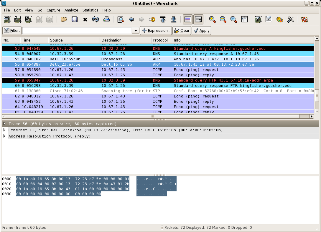
    ARP protocol screen capture. (On web site.) Ping of kingfisher from bluebird. Note multiple protocols:

    1. DNS -- A record lookup.

    2. ARP -- broadcast request, single destination response.

    3. DNS -- PTR record lookup.

    4. ICMP -- echo request/reply.

  4. Trace an IP datagram from one network to the next:

    \includegraphics{Figures/fig05_19.eps}

    Example: Send an HTTP request to a server on another subnet. (Resolver target on same subnet.)

Ethernet

  1. Originally, Ethernet was a shared access medium using thinwire (10B2) or thickwire (10B5) coaxial cabling:

    \includegraphics[width=4in]{Figures/fig05_20.eps}

  2. Then, we moved on to twisted-pair and hubs in a star topology:

    \includegraphics[width=3in]{Figures/fig05_21.eps}

    Hubs are physical layer devices (re-generate and broadcast) -- still a shared medium.

  3. Ethernet frame fields:

    \includegraphics{Figures/fig05_22.eps}

    1. Preamble (8 bytes): Used to synchronize receiver clocks with send clock.

      (Ethernet is asynchronous.)

    2. Type (2 bytes): Indicates which network layer protocol is contained in the frame's payload.

    3. Data: 46 to 1,500 bytes. Short frames are padded to 46 bytes. Padded bytes passed onto network layer.

      (IP uses datagram length to ignore padding.)

    4. CRC (4 bytes): error detection.

  4. Ethernet's CSMA/CD uses exponential backoff and random choice after back-to-back collisions:
    1. After 1st collision, wait $\{0, 1\} \times 512$ bit times.

    2. After 2nd, wait $\{0, 1, 2, 3\} \times 512$ bit times.

    3. After 3rd, wait $\{0, 1, \ldots, 7\} \times 512$ bit times.

    4. $\ldots$

    5. Maximum is $\{0, 1, \ldots, 1023\} \times 512$ bit times.

  5. Ethernet standards exist at both link and physical layers:

    \includegraphics[width=5in]{Figures/fig05_25.eps}

Link Layer Switches

\includegraphics[width=5in]{Figures/fig05_29.eps}

  1. Switches are intelligent, link layer devices.

    Store & forward.

    Eliminate collisions.

    Heterogeneous link speeds.

  2. Are transparent -- hosts aren't aware they're there.

    Don't have MAC addresses.

  3. Learn about the network, to eliminate broadcasting frames meant for one host.
    1. When a host first sends a frame, switch notes the source MAC address.

    2. Switch stores (MAC address, interface, timestamp) $n$-tuples in a table.

      Essentially, a small forwarding table.

      Multiple MAC addresses may be associated with the same interface. Why?

    3. On receipt of a frame, lookup the destination MAC address in the table.
      • If found, send the frame to the indicated interface.

      • Otherwise, broadcast the frame.

    4. Timestamp used to purge stale entries.


Thomas P. Kelliher 2011-04-29
Tom Kelliher