Transport Layer Congestion Control

Tom Kelliher, CS 325

Mar. 30, 2011

Administrivia

Announcements

Assignment

Read 4.1-4.3.

From Last Time

TCP Reliability.

Outline

  1. Congestion control principles.

  2. TCP congestion control.

Coming Up

Network layer introduction.

Congestion Control Principles

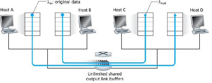
Two Senders; Single Router with Infinite Buffers

\includegraphics{Figures/fig03_43.eps}

  1. Assume no segments are dropped and senders don't time-out any segments -- no retransmits.

  2. The network load generated by each sender's application layer is $\lambda_{\rm in}$ bps.

    Assume the senders equally share the available bandwidth.
  3. The router's outgoing link has capacity R bps.

  4. The network load seen by the receiver's application layer is $\lambda_{\rm out}$ bps.

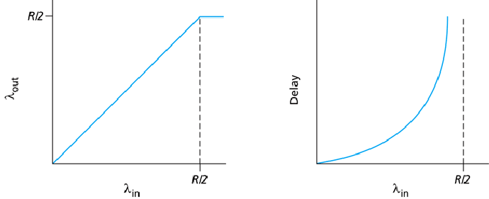
\includegraphics{Figures/fig03_44.eps}

  1. $\lambda_{\rm out} = \lambda_{\rm in}$ until we hit the bandwidth limit -- $R/2$ shared -- $\lambda_{\rm out}$ can't exceed this.

  2. As $\lambda_{\rm in}$ approaches $R/2$, the router's segment queue's length -- and delay -- increases.

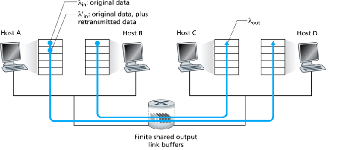
Two Senders; Single Router with Finite Buffers

\includegraphics{Figures/fig03_45.eps}

  1. Now, segments will be be dropped and retransmits will occur.

  2. $\lambda'_{\rm in}$ is the offered load of the transport layer.

    Due to retransmits, $\lambda'_{\rm in} \geq \lambda_{\rm in}$.

\includegraphics{Figures/fig03_46.eps}

  1. Due to finite buffers, $\lambda'_{\in}$ can't exceed $R/2$ -- shared link capacity.

    The graph on the left assumes the sender is omniscient and knows when the router has free buffers and only transmits segments then, avoiding dropped segments. -- unrealistic.

  2. Dropped segments mean duplicate, redundant data sent across a link -- wasting bandwidth.

    The middle graph shows what could happen if the sender retransmits only segments known to be lost -- again, unrealistic. Here, we assume 17% of segments are retransmits.

  3. Realistically, delays will cause some non-dropped segments to be retransmitted, further wasting bandwidth with redundant segments.

    The graph on the right shows this realistic scenario, assuming each segment is retransmitted once.
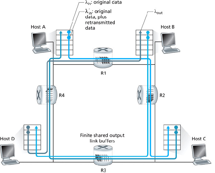
Four Senders; Multiple Routers with Finite Buffers; Multihop Routes

\includegraphics{Figures/fig03_47.eps}

  1. Consider what could happen if R2 becomes congested due to B-D traffic:
    1. R2 begins dropping segments from A-C, wasting bandwidth at R1.

    2. A's offered load increases, to handle retransmits.

    3. R1 could become congested, affecting the (initially free) D-B route.

Worst case, B-D traffic could completely lock-out A-C traffic beyond the point at which $\lambda'_{\rm in}$ saturates the routers' transmit capacity:

\includegraphics[width=3.5in]{Figures/fig03_48.eps}

Congestion Control Approaches

\includegraphics[width=4in]{Figures/fig03_49.eps}

Two approaches:

  1. End-to-end control:
    1. No help from network layer --sender/receiver have to intuit congestion on their own.

    2. TCP intuits congestion through fast retransmits (triple ACKs), not too bad -- some bandwidth still available; timeout transmits, really bad -- no bandwidth available.

      Third idea for TCP: increased RTTs mean congestion is beginning to become a problem.

  2. Network assisted. Two approaches here:
    1. Direct feedback with choke packet -- router sends choke command directly to sender.

    2. Indirect feedback with congestion indication bit in segment -- router sets this, when congested, as it forwards a segment to receiver.

      Receiver responsible for getting the indication back to the sender.

TCP Congestion Control

  1. Recall receive window for flow control:

    \begin{displaymath}
{\tt LastByteSent} - {\tt lastByteAcked} \leq {\tt RcvWindow}
\end{displaymath}

  2. Recall our transmit model: sender sends $n$ segments each RTT with $n \times {\tt MSS} = {\tt RcvWindow}$.

    We therefore have $\lambda'_{\rm in} = {\tt RcvWindow} / RTT$.

    So, RcvWindow, controlled by receiver, can be used to throttle sender rate.

  3. TCP itself defines CongWindow, maintained by sender, to throttle sender rate in face of congestion.

    We then have:

    \begin{displaymath}
{\tt LastByteSent} - {\tt lastByteAcked} \leq \min({\tt RcvWindow}, {\tt
CongWindow})
\end{displaymath}

    Sender rate controlled by both RcvWindow and CongWindow.

TCP congestion control algorithm:

  1. Multiplicative decrease:
    1. After triple duplicate ACK, cut CongWindow in half. CongWindow never drops below 1 MSS.

      Not as bad as a timeout.

    2. After a timeout, cut CongWindow down to 1 MSS.

  2. Additive increase:
    1. Increase CongWindow by 1 MSS each RTT.

      Increase rate is controlled by RTT -- a lower RTT results in faster CongWindow increase rate.

      Often implemented by increasing CongWindow by $1~{\rm MSS} \times
({\rm MSS}/{\tt CongWindow})$ for each new ACK.

    2. Actually, CongWindow increase is multiplicative until Threshold is reached.

    3. Additive increase; multiplicative decrease:

      \includegraphics[width=5in]{Figures/fig03_51.eps}

  3. Slow start:
    1. CongWindow is set to 1 MSS for a new connection.

    2. CongWindow is increased by 1 MSS for each ACK received, until Threshold is reached.

      Exponential increase in CongWindow during SS phase:

      \includegraphics[width=4in]{Figures/fig03_52.eps}

    3. Additive increase, once Threshold reached:

      \includegraphics[width=4in]{Figures/fig03_53.eps}

      TCP Reno = current algorithm. Is decrease from timeout or fast retransmit?

  4. Actual timeout events behavior:

    State Event Sender Action Comment
    Slow Start (SS) New ACK received CongWin = CongWin + MSS. if (CongWin $>$ Threshold) set state to CA. CongWin doubles every RTT.
    Congestion Avoidance (CA) New ACK received CongWin = CongWin + MSS(MSS/CongWin) CongWin increases by 1 MSS every RTT.
    SS or CA Triple Dup ACK Threshold = CongWin/2. CongWin = Threshold. set state to CA. Fast recover; multiplicative decrease.
    SS or CA Timeout Threshold = CongWin/2. CongWin = 1 MSS. Set state to SS.
    SS or CA Duplicate ACK received Increment duplicate ACK count for segment

Fairness

  1. Is TCP's AIMD algorithm fair? Consider this situation:

    \includegraphics[width=4in]{Figures/fig03_54.eps}

    Suppose, initially, connection 1 has a higher throughput (CongWindow) than connection 2:

    \includegraphics[width=4in]{Figures/fig03_55.eps}

    This shows what happens during 3DupACK events -- multiplicative decrease. Eventually, we converge to equal throughput.

    On timeout, both connections will end up with a CongWindow of 1 MSS.

  2. But, UDP doesn't implement congestion control, which can bring a network down.

  3. Also, what about parallel TCP connections -- they allow a connection to grab more bandwidth. Fair?


Thomas P. Kelliher 2011-03-29
Tom Kelliher