![\includegraphics[width=4in]{Figures/fig04_01.eps}](apr06img1.png)
Tom Kelliher, CS 325
Apr. 6, 2011
Read 4.4.
Congestion Control.
IP.
Forwarding vs. routing:
The forwarding table determines this routing.
The output from the routing algorithms are used to configure the forwarding tables. As such, they determine the host-to-host routes.
![\includegraphics[width=4in]{Figures/fig04_02.eps}](apr06img2.png)
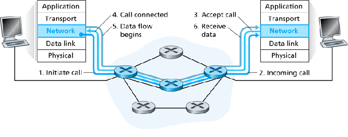
Routers also participate in connection setup for network-layer protocols based on the virtual circuit model, such as ATM.
Possible network service characteristics, WRT individual packets:
Possible network service characteristics, WRT packet flows:
The Internet gives ``best effort'' service. ``Best effort'' is a euphemism for ``No guarantees.'' ATM provides a couple different service levels:
| Network Architecture | Service Model | Bandwidth Guarantee | No-Loss Guarantee | Ordering | Timing | Congestion Indication |
| Internet | Best effort | None | None | Any order possible | Not maintained | None |
| ATM | CBR | Guaranteed constant rate | Yes | In order | Maintained | Congestion will not occur |
| ATM | ABR | Guaranteed minimum | None | In order | Not maintained | Congestion indication provided |
Recall:
Consider the following example of a small virtual circuit network:
![\includegraphics[width=4in]{Figures/fig04_03.eps}](apr06img3.png)
and R1's routing table:
| Incoming Interface | Incoming VC # | Outgoing Interface | Outgoing VC # |
| 1 | 12 | 2 | 22 |
| 2 | 63 | 1 | 18 |
| 3 | 7 | 2 | 17 |
| 1 | 97 | 3 | 87 |
Why?
Three phases in the life of a virtual circuit:
No setup or teardown. Source just ``dumps'' packets into the network:
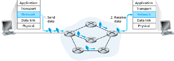
Routers must forward packets on incoming links to correct outgoing links.
Example: IP. 32 bit address. A complete forwarding table would have
![]() entries. Infeasible.
entries. Infeasible.
Instead, use hierarchical addressing and ``blocks'' of addresses:
| Destination Address Range | Link Interface |
| 11001000 00010111 00010000 00000000 | |
| through | 0 |
| 11001000 00010111 00010111 11111111 | |
| 11001000 00010111 00011000 00000000 | |
| through | 1 |
| 11001000 00010111 00011000 11111111 | |
| 11001000 00010111 00011001 00000000 | |
| through | 2 |
| 11001000 00010111 00011111 11111111 | |
| otherwise | 3 |
This table can be compressed to this:
| Prefix Match | Link Interface |
| 11001000 00010111 00010 | 0 |
| 11001000 00010111 00011000 | 1 |
| 11001000 00010111 00011 | 2 |
| otherwise | 3 |
Dumb edge devices, smart core devices.
Smart edge devices. Pushing functionality to the edge increases innovation. Keep core devices simple.
Of course, we have only ``best effort'' service, due to this simplicity in the core.
bluebird:~/
* netstat -r
Kernel IP routing table
Destination  Gateway    Genmask         Flags   MSS Window  irtt  Iface
10.67.1.0    *          255.255.255.0   U         0 0          0  eth0
169.254.0.0  *          255.255.0.0     U         0 0          0  eth0
default      10.67.1.1  0.0.0.0         UG        0 0          0  eth0
Block diagram of a router:

A bit more detail on an input port:
![\includegraphics[width=5in]{Figures/fig04_07.eps}](apr06img8.png)
High-end routers use CAMs.
Switching fabric architectures:
Some dedicated routers use this architecture.
![\includegraphics[width=4in]{Figures/fig04_08a.eps}](apr06img9.png)
Higher performance than memory-based. Not uncommon in mid-level (enterprise) dedicated routers.
![\includegraphics[width=4in]{Figures/fig04_08c.eps}](apr06img10.png)
More sophisticated configurations, such as omega networks, are coming into use.
Highest performance. Backbone routers would tend to use this architecture.
![\includegraphics[width=3in]{Figures/fig04_08b.eps}](apr06img11.png)
Output port details:
![\includegraphics[width=5in]{Figures/fig04_09.eps}](apr06img12.png)
Switching fabric can dump packets into an output port more quickly than it can off-load them into the link, hence the need for queuing.
Switching fabric simultaneously forwarding three packets to the same output port:
![\includegraphics[width=5in]{Figures/fig04_10.eps}](apr06img13.png)
Head-of-the-line (HOL) blocking:
![\includegraphics[width=5in]{Figures/fig04_11.eps}](apr06img14.png)
Second packet in bottom input port blocked, even though its output port is available, because first packet is blocked.
HOL blocking can result in serious queueing problems.