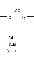
SO = SI four clocks later.
Using 2-1 muxes, how would you modify this to incorporate a shift control signal?

D and Q are buses.
Tom Kelliher, CS 240
Apr. 28, 2010
Assignment due now.
Read 7-6, 7-11.
Registers
Counters

SO = SI four clocks later.
Using 2-1 muxes, how would you modify this to incorporate a shift control signal?

D and Q are buses.
If A and B are ![]() bits, the output can be how many bits?
bits, the output can be how many bits?
Use this to design a sequential circuit which takes A as serial input and outputs 3A.
Parallel load, shift left or right, hold.
-- Parallel load shift register.  Shift left or right.
-- Mode bits:
--    00: hold
--    01: load
--    10: shift left (toward msb)
--    11: shift right (toward lsb)
--
-- msi: most significant shift in.
-- lsi: least significant shift in.

library ieee;
use ieee.std_logic_1164.all;

entity shift_reg is

  port (
    d            : in  std_logic_vector (31 downto 0);
    mode         : in  std_logic_vector (1 downto 0);
    clk, reset_n : in  std_logic;
    msi, lsi     : in  std_logic;
    q            : out std_logic_vector (31 downto 0));

end shift_reg;

architecture behavioral of shift_reg is

  signal state : std_logic_vector (31 downto 0);

begin  -- behavioral

  q <= state;                           -- Update output.

  state_register: process (clk, reset_n)
  begin  -- process state_register
    if reset_n = '0' then               -- asynchronous reset (active low)
      state <= X"00000000";
    elsif clk'event and clk = '1' then  -- rising clock edge
      if mode = "00" then               -- Hold.
        state <= state;
      elsif mode = "01" then            -- Load.
        state <= d;
      elsif mode = "10" then            -- Shift left.
        state <= state (30 downto 0) & lsi;
      else                              -- Shift right.
        state <= msi & state (31 downto 1);
      end if;
    end if;
  end process state_register;

end behavioral;