Tom Kelliher, CS 220
Oct. 24 ,2001
Sign up sheets available for green and yellow in X Lab for Thursday and Friday.
Practice session for ACM programming contest this Saturday at 10:00 AM in X Lab.
Read 4-4.
Sequential circuits and latches.
Sequential circuit analysis.
Must use two-phase, etc. clocking.
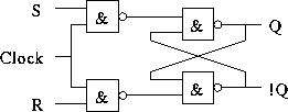
Clocked SR latch:

Analyze Q, !Q with these input waveforms. Assume Q low initially.

Master-Slave device: ensures no transparency. While master (leading latch) is transparent, slave is latched and vice-versa.
When J and K are both high, toggles in a controlled manner.
Diagram:
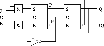
Analyze P, !P, Q, and !Q with these input waveforms. Assume Q low initially.

Changes state on edge, but not edge-triggered: one's catching.
Edge-triggered: samples input only during a clock transition.
Rising edge triggered D flip-flop. Figure 4-13 uses eight NAND gates and three inverters (verify for yourself). A slight improvement:
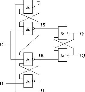
Analyze Q, !Q, !R, !S, T, and U with these input waveforms. Assume Q low initially.

Any one's catching?
Compact way of representing flip-flop behavior.
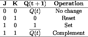
Clock edge is implied in the transition from t to t + 1.

Always loads. To control loading, use this circuit:
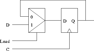
Gating the clock signal leads to problems.