Tom Kelliher, CS26
Oct. 22, 1996
How does a computer look from ``underneath the covers?''
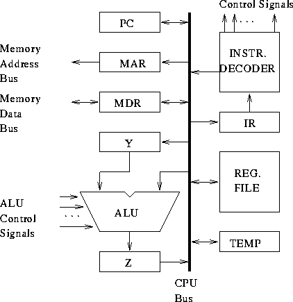
Fundamental internal CPU registers (not seen by programmer):
Two fundamental combinational circuits:

IR = (PC) and PC increment
PC = PC + 1. What is `` 1''?
Instruction or data.
MAR = (REGx), Read         # 1 clock
WMFC                       # ? clocks
MDR = mem. data bus        # 1 clock
REGy = (MDR)               # 1 clock
MAR = (REGx)                        # 1 clock
MDR = (REGy), Assert write signal   # 1 clock
WMFC                                # ? clocks
Register file:
Assert address, load signal # 1 clock
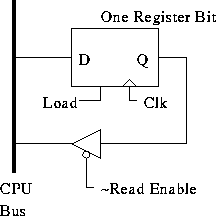
Scalar register:
Assert load signal # 1 clock
Register file:
Assert address, read enable # 1 clock
Scalar register:
Assert read enable # 1 clock
Read enable?

Y = (REGx)
BUS = (REGy), ALU-op, Z = ALUout
REGz = Z
Adding 1?
Consider the execution of:
ADD (R3), R1
High-level execution sequence:
Detailed control sequencing:
1: PCout, MARin, Read, Clear Y, Set carry-in to ALU, Add, Zin
2: Zout, PCin, WMFC
3: MDRout, IRin
4: R3out, MARin, Read
5: R1out, Yin, WMFC
6: MDRout, Add, Zin
Zout, R1in, END
Consider the execution of:
BR ENDIFAssume PC-relative addressing is used.
High-level execution sequence:
Detailed control sequencing:
1: PCout, MARin, Read, Clear Y, Set carry-in to ALU, Add, Zin
2: Zout, PCin, WMFC
3: MDRout, IRin
4: PCout, Yin
5: Offset-field-of-IRout, Add, Zin
Zout, PCin, End
What about conditional branches?
Consider the execution of:
BZ ENDFOR
High-level execution sequence:
Detailed control sequencing:
1: PCout, MARin, Read, Clear Y, Set carry-in to ALU, Add, Zin
2: Zout, PCin, WMFC
3: MDRout, IRin
4: PCout, Yin, if Z = 0 then End
5: Offset-field-of-IRout, Add, Zin
6: Zout, PCin, End
Executing instruction requires executing sub-instructions. How is this controlled?
Two ways of designing CPU control:
What are the inputs to the controller?
Controller block diagram:

Some control equations:
PCout = T1 + ...

MARin = T1 + T4*ADD*MEMORY_OPERAND + ...

Zin = T1 + T6*ADD + T5*(BR + BZ) + ...
Asynchronous interface.
How does the CPU wait? What about the sub-cycle counter?
Refer to Fig. 3.11. For memory operations, need a circuit which:
Equations:
MR = Read + Readff
Readff.set = Read
Readff.reset = MFC

MW = Write + Writeff
Writeff.set = Write
Writeff.reset = MFC

Run = ~WMFC + MFC
1: PCout, MARin, Read, Clear Y, Set carry-in to ALU, Add, Zin
2: Zout, PCin, WMFC
...
MR + MW term in RUN.