A Single-Cycle Implementation
Tom Kelliher, CS 240
Mar. 25, 2002
Homework due Wednesday.
Read 5.4.
Merging the datapaths.
- A simple implementation scheme.
- The control unit.
- Setting the control signals.
A multi-cycle implementation.
The final, combined datapath:
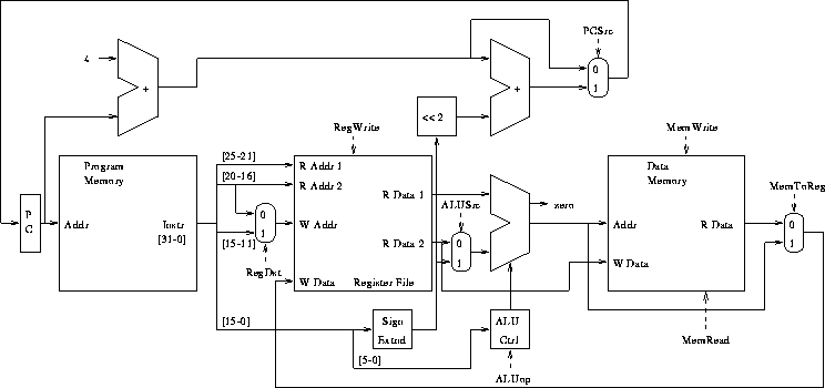
Instructions implemented:
- lw, sw.
- beq.
- add, sub, and, or, slt.
Recall ALU control inputs:
- 000 --- AND.
- 001 --- OR.
- 010 --- add.
- 110 --- subtract.
- 111 --- slt.
ALU op signals:
- 00 --- lw, sw.
- 01 --- beq.
- 10 --- R-format.
(Why did we choose this encoding?)
Funct field for R-format instructions:
- 100000 --- add.
- 100010 --- subtract.
- 100100 --- and.
- 100101 --- or.
- 101010 --- slt.
Note: no Funct field for other instructions.
Truth table for ALU control outputs?
- RegDst --- selects rt or rd field as write address.
- RegWrite --- write enable.
- ALUsrc --- selects rd2 or immediate data.
- PCSrc --- selects PC + 4 or branch target.
- MemRead --- read enable.
- MemWrite --- write enable.
- MemToReg --- selects ALU output or memory data to register file write
data port.
- Is it combinational or sequential?
- Why are its only inputs the opcode bits?
The control unit in place:
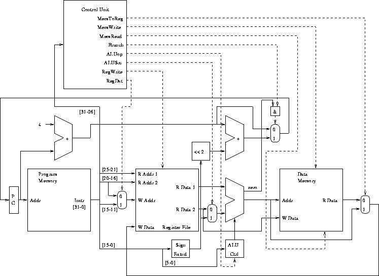
How should the control signals be set (0, 1, x) for each of the following?
- R-format instructions.
- lw.
- sw.
- beq.
Thomas P. Kelliher
Tue Mar 19 14:30:20 EST 2002
Tom Kelliher