![\includegraphics[width=4in]{Figures/alu.eps}](hw06img1.png)
Tom Kelliher, CS 240
25 points, due April. 6
For this assignment, you will be implementing in VHDL and simulating an eight-bit version of the simplified arithmetic logic unit (ALU) used in Patterson & Hennessy's Computer Organization & Design textbook. Use the following for the top-level entity I/O structure of your ALU:
entity alu8 is
    Port ( a        : in   STD_LOGIC_VECTOR (7 downto 0);
           b        : in   STD_LOGIC_VECTOR (7 downto 0);
           op       : in   STD_LOGIC_VECTOR (2 downto 0);
           result   : out  STD_LOGIC_VECTOR (7 downto 0);
           overflow : out  STD_LOGIC
         );
end alu;
The functions to be computed by the ALU are defined by:
if (op == 0)
   result = a AND b;
else if (op == 1)
   result = a OR b;
else if (op == 2)
   result = a NAND b;
else if (op == 3)
   result = a NOR b;
else if (op == 4)
{
   result = a + b;
   if (overflow has occurred)
      overflow = 1;
   else
      overflow = 0;
}
else if (op == 5)
{
   result = a - b;
   if (overflow has occurred)
      overflow = 1;
   else
      overflow = 0;
}
else if (op == 6)   // set on less than AKA slt
   if (a < b)
      result = 1;
   else
      result = 0;
For those ops for which overflow is not defined, you may assume that
it is a don't care. (Don't read too much into this -- it simply means
that you only need be concerned with overflow's value being correct
for the addition and subtraction operations.) You may assume that op's value will never be 7.
The eight-bit ALU just described can be broken down into eight one-bit ALUs and some combinational control logic. Use this entity statement for the one-bit ALU:
entity alu1 is
   Port ( a         : in  STD_LOGIC;
          b         : in  STD_LOGIC;
          less      : in  STD_LOGIC;
          ainvert   : in  STD_LOGIC;
          binvert   : in  STD_LOGIC;
          carryin   : in  STD_LOGIC;
          operation : in  STD_LOGIC_VECTOR (1 downto 0);
          result    : out STD_LOGIC;
          carryout  : out STD_LOGIC;
          sign      : out STD_LOGIC
        );
The following block diagram illustrates nearly all of the functionality
required of the one-bit ALU. The one missing piece is the sign output
defined in the above entity statement. Use the sum output directly from
the one-bit full adder to produce the sign bit.
Two small pieces of combinational logic are necessary. The first of these
generates the control signals needed by the one-bit ALUs from the op
input of the eight-bit ALU:
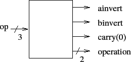
The values of these output signals, needed by the one-bit ALUs, are
completely determined by the value of op.
For example, if op is 011 (NOR), then both ainvert
and binvert should be 1, carry(0) is a don't care,
and operation should be 00, selecting the value of the AND
gate as the output of the mux.
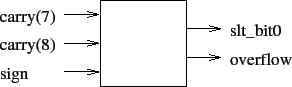
The second piece of combinational logic is used to generate bit 0 of
result for the slt instruction and to generate the
overflow output:
Some hints:
result for the slt instruction.
slt instruction should work correctly for all values of
a and b, even if overflow
occurs. Remember, overflow indicates that the sign bit is wrong.
a and
b within the one-bit ALU can be replaced with fan-in 2 EXOR
gates. (VHDL has an xor operator.)
sign outputs of the seven least significant one-bit ALUs
will be unneeded in the eight-bit ALU. You may use the open
keyword in the port map lists for those seven ALUs to indicate that the
sign output should be left unconnected.
Turn in your VHDL source code (module files and test bench files), your test waveforms from ISim, and a brief commentary defending your choice of test bench test cases as demonstrating the correctness of your eight-bit ALU.