Carry Lookahead and Signed-Digit Addition
Tom Kelliher, CS 240
Feb. 27, 2006
Read 4.7 and 5.7.
Addition limits.
- Carry lookahead addition.
- Signed digit representations.
Introduction to VHDL.
- Now, we demonstrate a feasible
 adder.
- Recall:
- Carry generate:
 .
.
- Carry propagate:
 .
.
Restricting the carry computation circuitry to a tree structure:
- Leaves: Four-bit carry lookahead adders.
- Non-Leaves: Four-bit carry lookahead group units.
- Design a four-bit full carry lookahead adder.
Block diagram:
Block generate, propagate.
- What is the fan-in?
- What is the delay model from inputs to outputs?
- Design a 4-Group carry lookahead unit.
Block diagram:
Use of block generates, propagates.
- What is the fan-in?
- What is the delay model from inputs to outputs?
Total gate delays for ripple-carry adder.
Gate delays for cascaded and full carry lookahead adders.
- Consider the digit set of the maximally redundant signed digit
representation for radix
 :
:
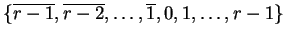
- For radix 2 we have:
 .
.
Radix 4:
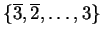 .
.
- For some values, there are multiple representations. For example:
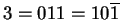 (radix 2).
- This redundancy can be exploited so that we can design constant time signed
digit adders.
- Idea: Ensure that a carry propagates no further than two bit positions.
- Circuit sketch:
- Stage 1 adder addition table:
| Addend + Augend |
Carry |
Sum |
 |
 |
0 |
|
|
1 |
| 0 |
0 |
0 |
| 1 |
0 |
1 |
| 2 |
0 |
2 |
Goal: Ensure sums are  and carries are
  .
.
- Stage 2 adder addition table:
| Addend + Augend |
Carry |
Sum |
|
0 |
|
| 0 |
0 |
0 |
| 1 |
1 |
|
| 2 |
1 |
0 |
Goal: Ensure sums are and carries are .
- Final stage addition table:
| Addend + Augend |
Carry |
Sum |
|
0 |
|
| 0 |
0 |
0 |
| 1 |
0 |
1 |
Thomas P. Kelliher
2006-02-26
Tom Kelliher
![\begin{figure}\centering\includegraphics[width=6in]{Figures/carryTree.eps}\end{figure}](feb27img4.png)
![\begin{figure}\centering\includegraphics[]{Figures/carrylookahead.eps}\end{figure}](feb27img5.png)
![\begin{figure}\centering\includegraphics[]{Figures/lookaheadunit.eps}\end{figure}](feb27img6.png)
![\begin{figure}\centering\includegraphics[width=6in]{Figures/sdAdder.eps}\end{figure}](feb27img12.png)